*********************************************************************************************************************************************
AUGUST 2025 UPDATE
*********************************************************************************************************************************************
ALAN DEWEY
*********************************************************************************************************************************************
KARL CROWTHER
With
these sections glued down onto the baseboards, foamboard profile pieces were installed at
something like 100-150mm intervals, after which further pieces of foamboard were individually
cut to fill in the gaps. On the real thing, these banks are surfaced with what is in effect,
dry stone walling laid on its side, so I will have to work out a way of representing this….
*********************************************************************************************************************************************
ANDY LEE
*********************************************************************************************************************************************
STEVE CARTER
*********************************************************************************************************************************************
KIER HARDY
*********************************************************************************************************************************************
HYWEL THOMAS
*********************************************************************************************************************************************
*********************************************************************************************************************************************
![]()
 A snatched photo of Whitley sidings in natural light in the school conservatory on a hot day
in Norwich during April 2025. It was a busy first time out where the layout was well received.
The next outing for Whitley is at Rail-ex East at Cambridge in September.
A snatched photo of Whitley sidings in natural light in the school conservatory on a hot day
in Norwich during April 2025. It was a busy first time out where the layout was well received.
The next outing for Whitley is at Rail-ex East at Cambridge in September.
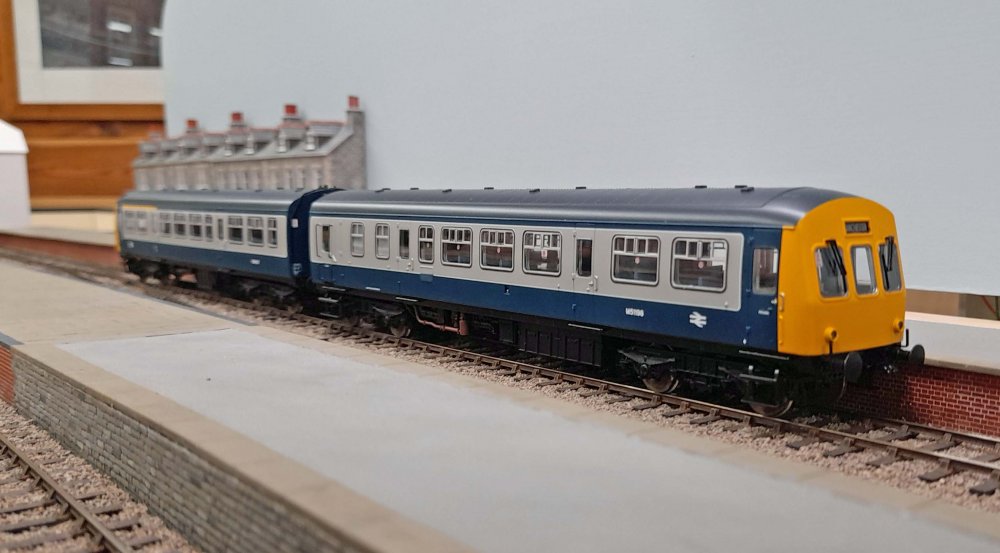
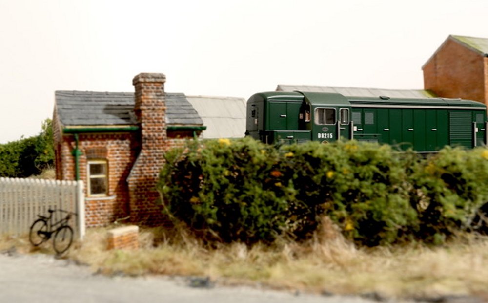 Whitley station crossing hut with a BTH type 1 number D8215 passing through. Photography for
the recent MRJ article highlighted the need for more weathering on the stock, as this image
illustrates the point well with the 'out of the box' finish.
Whitley station crossing hut with a BTH type 1 number D8215 passing through. Photography for
the recent MRJ article highlighted the need for more weathering on the stock, as this image
illustrates the point well with the 'out of the box' finish.
![]()
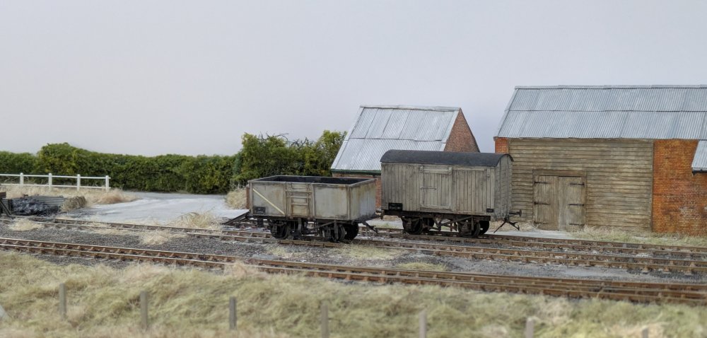
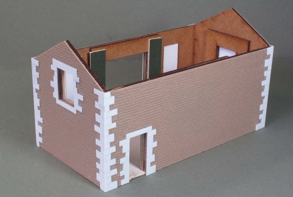 Apologies for a lack of a presence last month – a bout of Covid put paid to plans! Some
progress has been made on the field barn featured last time; here the stone quoins and
lintels have been added, built up from strips of 15 thou Plastikard.
Apologies for a lack of a presence last month – a bout of Covid put paid to plans! Some
progress has been made on the field barn featured last time; here the stone quoins and
lintels have been added, built up from strips of 15 thou Plastikard.
 Once the glue had set, work commenced on scribing surface detail into the stonework –
though the effect not especially noticeable in the photos.
Once the glue had set, work commenced on scribing surface detail into the stonework –
though the effect not especially noticeable in the photos.
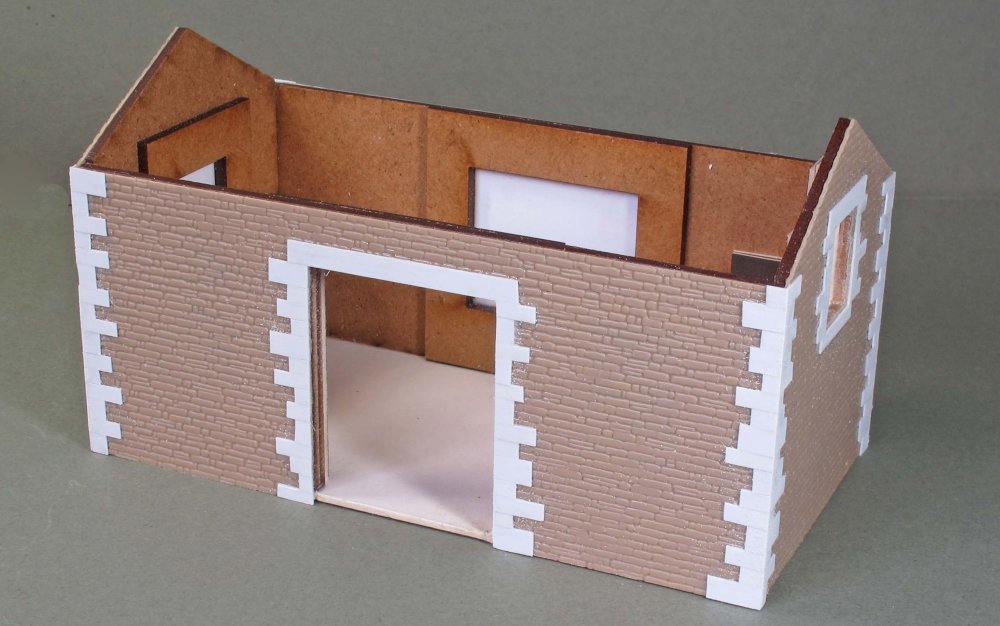
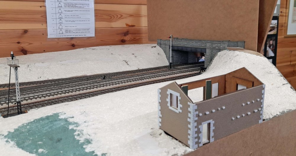 The model poised in its intended location on the layout, various ‘through stones’ having
been added – these were again carved to irregular shapes once the glue had gardened.
The model poised in its intended location on the layout, various ‘through stones’ having
been added – these were again carved to irregular shapes once the glue had gardened.
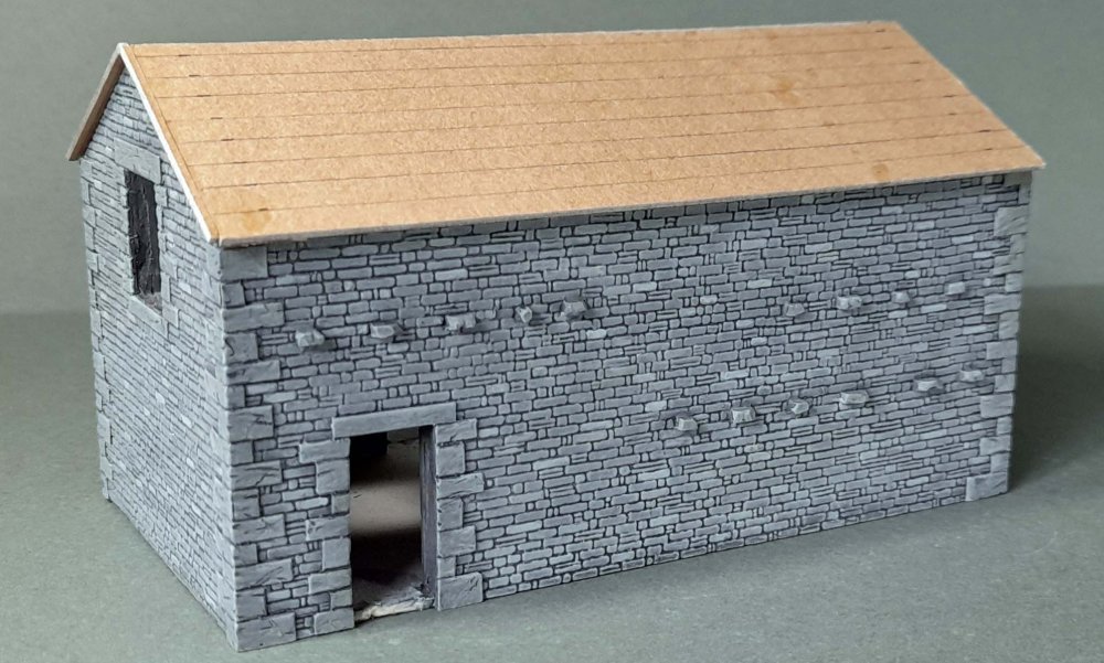 The completed walls were given a base coat comprising a roughly 50/50 mix of Humbrol Matt
64 and 147 and left to fully dry for several days. Then blackish wash (thinned around 50%)
was applied and after a few minutes the surface of the stones wiped with kitchen towel. The
model was then dry-brushed with the original stone colour mix and finally various stones were
picked out with slightly differing shades. The texturing of the quoin stones shows up better here.
The completed walls were given a base coat comprising a roughly 50/50 mix of Humbrol Matt
64 and 147 and left to fully dry for several days. Then blackish wash (thinned around 50%)
was applied and after a few minutes the surface of the stones wiped with kitchen towel. The
model was then dry-brushed with the original stone colour mix and finally various stones were
picked out with slightly differing shades. The texturing of the quoin stones shows up better here.
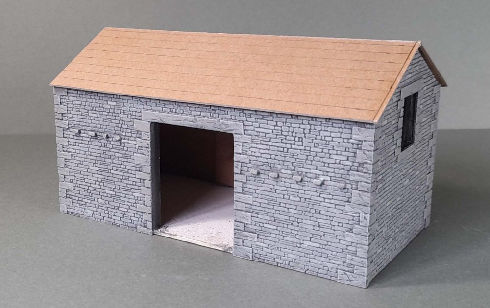 The roof is card (the old MRJ packing envelopes) ready to have paper slates attached, while I
mull over the interior. I’ve found a useful website that gives some interior shots of barns,
so maybe will try and represent some of this…
The roof is card (the old MRJ packing envelopes) ready to have paper slates attached, while I
mull over the interior. I’ve found a useful website that gives some interior shots of barns,
so maybe will try and represent some of this…
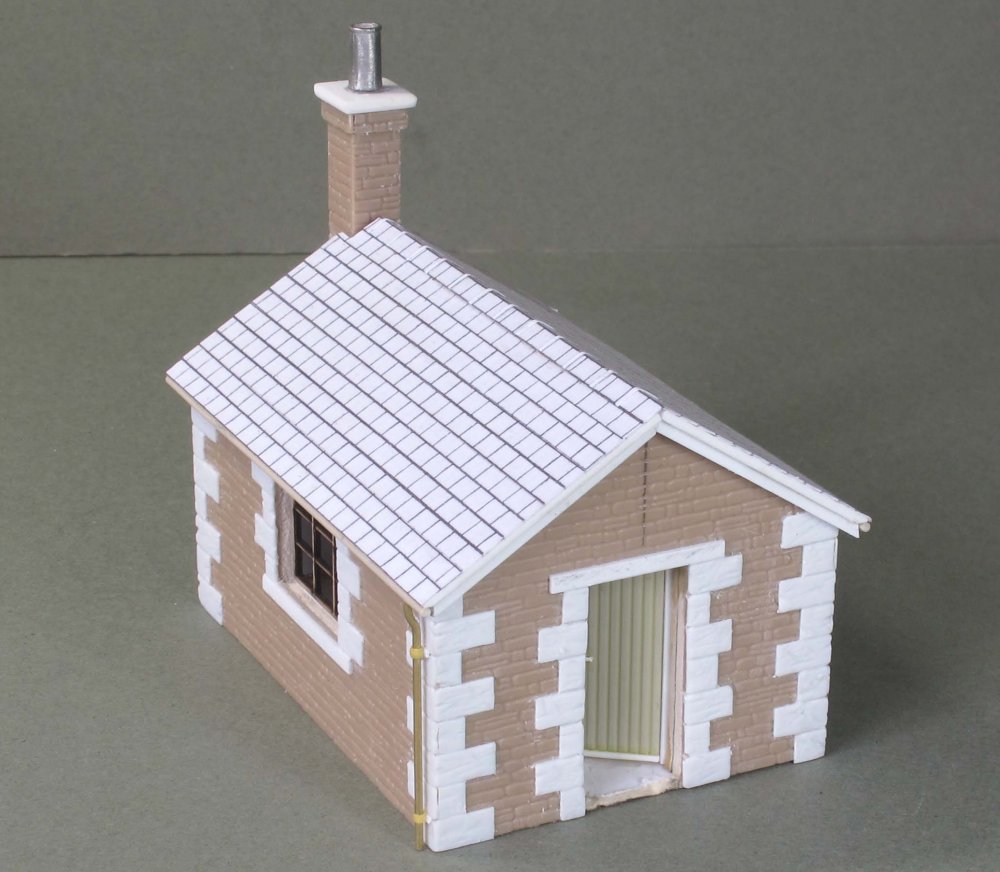 A further structure for the layout is this platelayers’ cabin – again the Furness appear to
have gone to town with what has a very utilitarian structure. Arnside viaduct had two of these,
one at each end. The model is card-based, again with Plastikard cladding and quoins as with
the barn. Given I had no dimensions it was guesswork from photos.
A further structure for the layout is this platelayers’ cabin – again the Furness appear to
have gone to town with what has a very utilitarian structure. Arnside viaduct had two of these,
one at each end. The model is card-based, again with Plastikard cladding and quoins as with
the barn. Given I had no dimensions it was guesswork from photos.
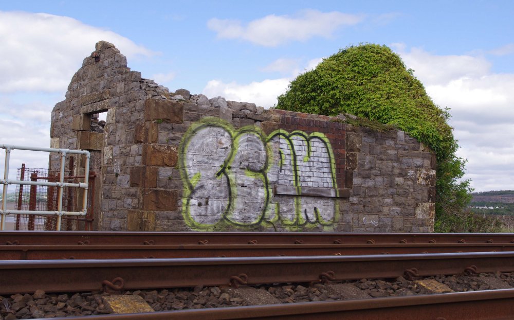 I used the past tense in the last photo, but actually the structures still remain, just! This
is the one at the Arnside end of the viaduct. You can see it has quoins of red sandstone,
something I was keen to replicate, though not the graffiti!
I used the past tense in the last photo, but actually the structures still remain, just! This
is the one at the Arnside end of the viaduct. You can see it has quoins of red sandstone,
something I was keen to replicate, though not the graffiti!
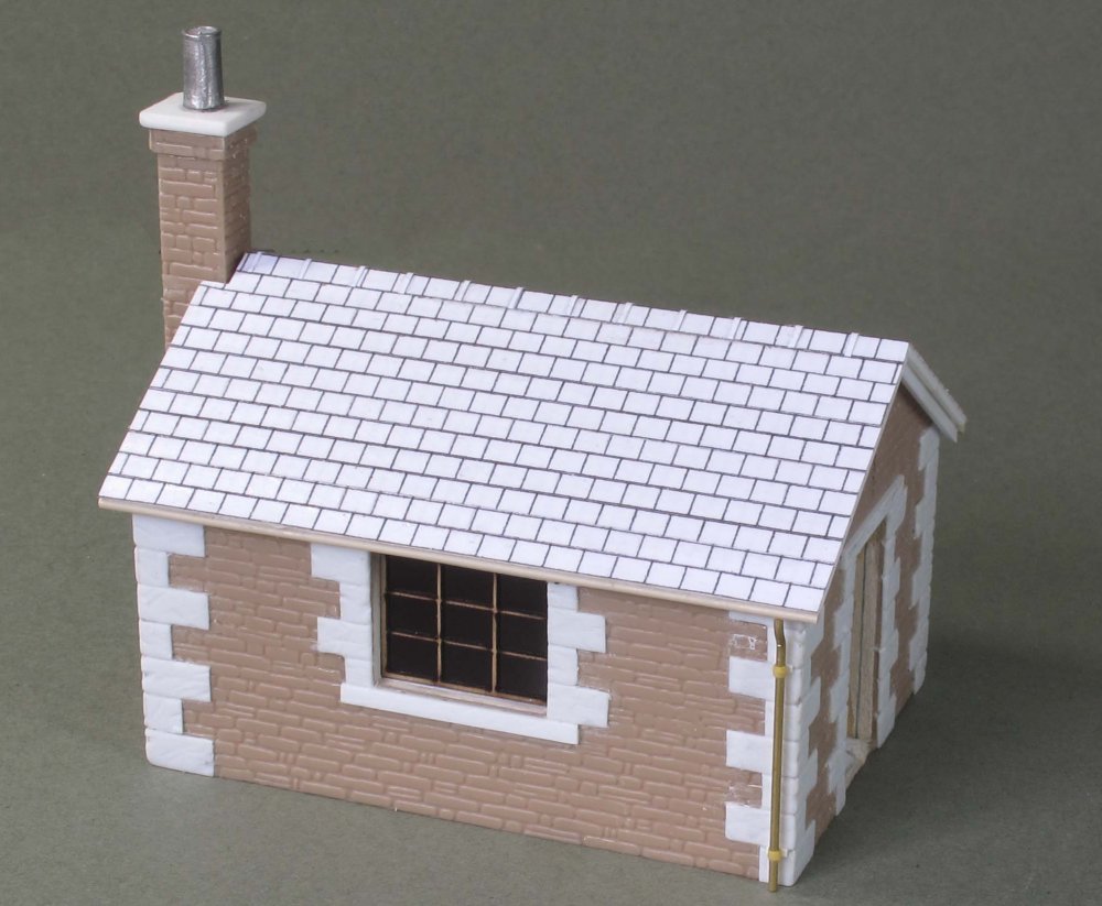 The window having been bricked up on the original structure I raided the laser cut parts I
had left over from Hebble Vale and came up with something that looks rather ‘Crittal’ in style.
Not sure how accurate it is, but looks about right to me.
The window having been bricked up on the original structure I raided the laser cut parts I
had left over from Hebble Vale and came up with something that looks rather ‘Crittal’ in style.
Not sure how accurate it is, but looks about right to me.
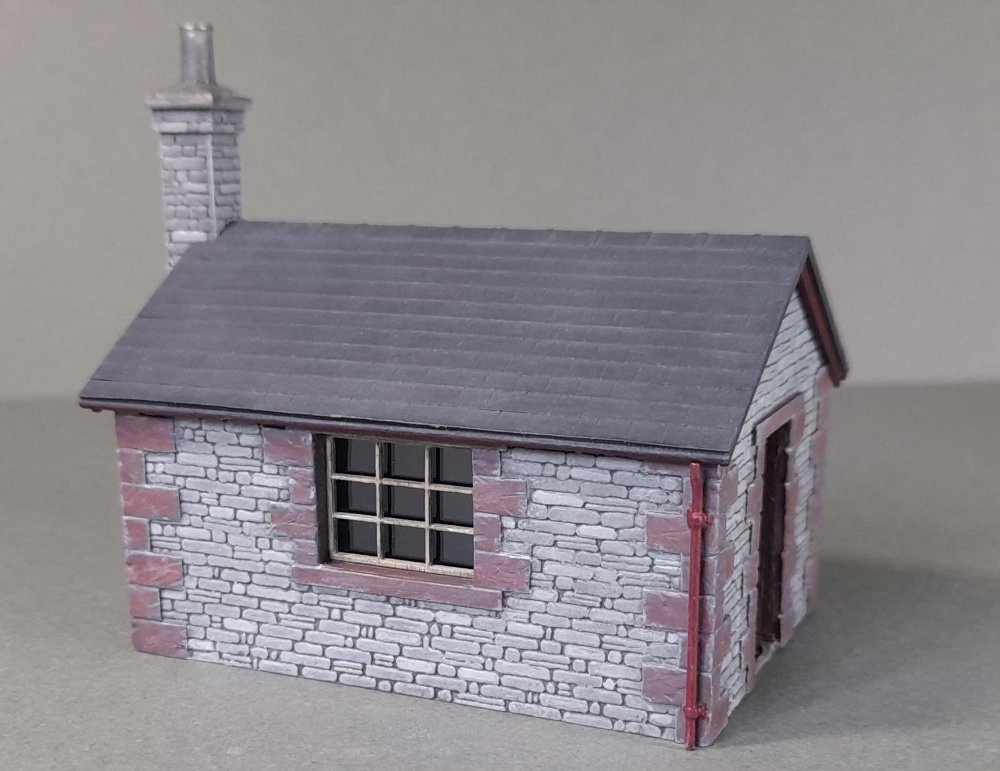 And here is the final result, basically decorated as for the stone barn, but with Humbrol 70
for the quoins. Not sure as yet about an interior, which explains why there’s no chimney
flashing at present as the roof isn’t yet fixed on.
And here is the final result, basically decorated as for the stone barn, but with Humbrol 70
for the quoins. Not sure as yet about an interior, which explains why there’s no chimney
flashing at present as the roof isn’t yet fixed on.
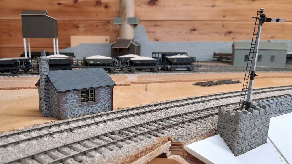 And on the layout, the platelayers’ cabin will be sited something like as shown here – at the
end of the viaduct as in the prototype.
And on the layout, the platelayers’ cabin will be sited something like as shown here – at the
end of the viaduct as in the prototype.
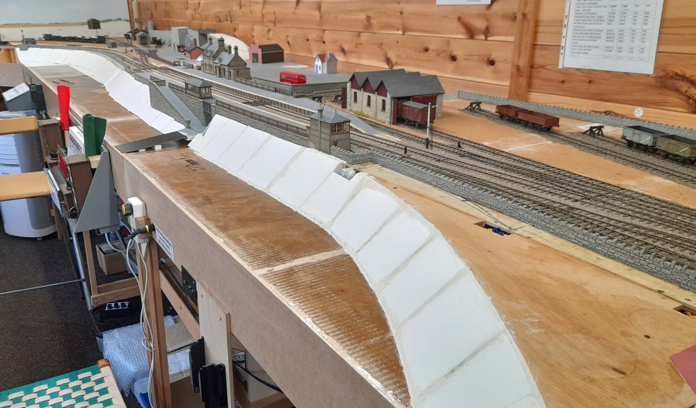 A major scenic development these past couple of months has been ‘blocking in’ the estuary
frontage alongside Kentside station – no more gaping holes through the baseboards at long last!
I deliberated how to form the horizontal surface and decided to use recycled corrugated packing
cardboard. On the underside, 20mm deep strips, cut across the corrugations were glued – around
the edges and in a cross-shaped pattern within, and an amazingly robust structure was obtained.
This was then treated with two coats of varnish to guard against the effect of moisture.
A major scenic development these past couple of months has been ‘blocking in’ the estuary
frontage alongside Kentside station – no more gaping holes through the baseboards at long last!
I deliberated how to form the horizontal surface and decided to use recycled corrugated packing
cardboard. On the underside, 20mm deep strips, cut across the corrugations were glued – around
the edges and in a cross-shaped pattern within, and an amazingly robust structure was obtained.
This was then treated with two coats of varnish to guard against the effect of moisture. 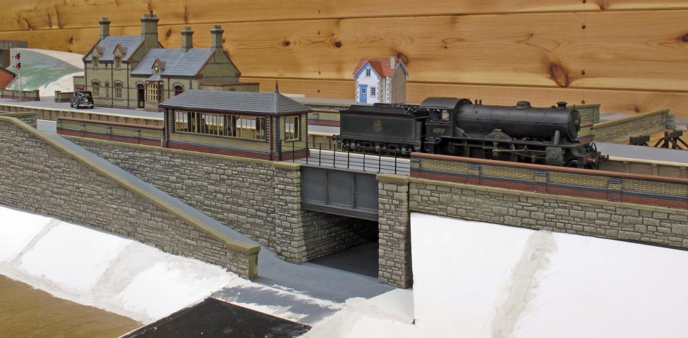 This is how the underpass at Kentside will lead down onto the estuary. The D49 was a PDK kit on
test, built for a customer, which has turned out very nicely.
This is how the underpass at Kentside will lead down onto the estuary. The D49 was a PDK kit on
test, built for a customer, which has turned out very nicely.
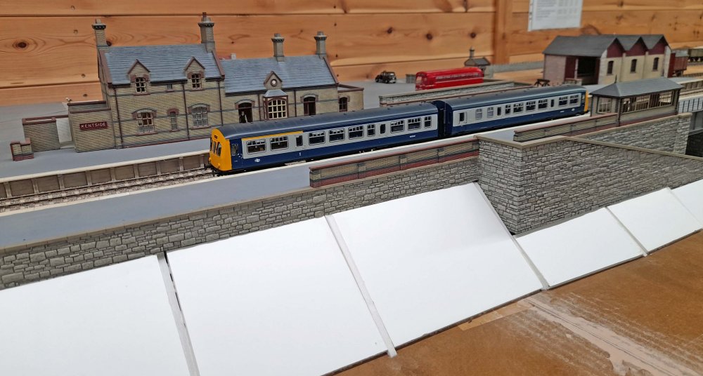 And something much more modern, this is Norman Pedley’s Bachmann Class 101 DMU which he brought
along to a recent operating session, converted to EM using Black Beetle wheelsets. The construction
of the banking shows up well here, any gaps being later filled in with Das modelling clay.
And something much more modern, this is Norman Pedley’s Bachmann Class 101 DMU which he brought
along to a recent operating session, converted to EM using Black Beetle wheelsets. The construction
of the banking shows up well here, any gaps being later filled in with Das modelling clay.
 And finally, the Class 101 DMU having arrived at Kendal Castle….
![]()
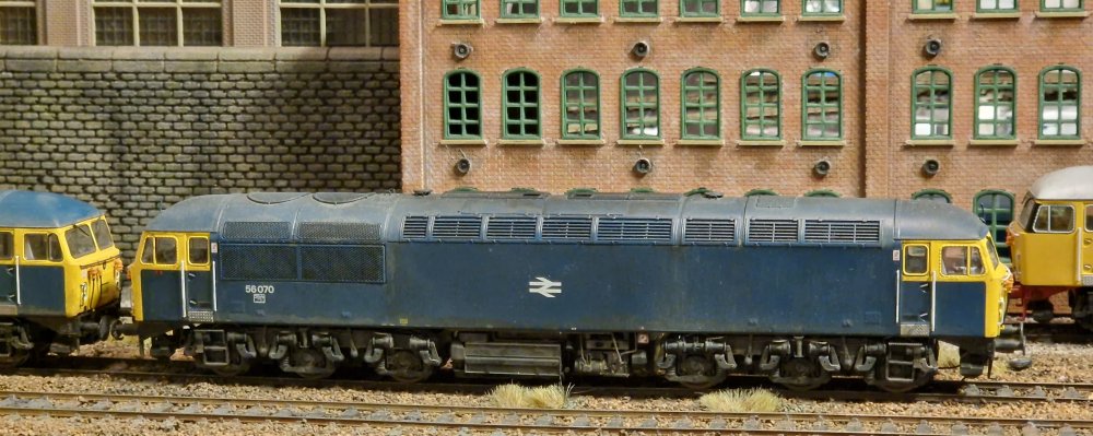 Another Cavalex Class 56 joins the fleet, with the replacement EM wheels dropping in very easily.
This is a Doncaster built loco and I wanted it to look very different from 56008 which I had
weathered the other month, continuing with my quest to make loco weathering different so they
don't all look like they went through the same puddle. I used some Railmatch frame dirt and
roof dirt rather than sleeper grime for the weathering. It was built up in layers with 50%
IPA washes using the alcohol bleaching that happens with this technique. All painted on with a
chisel brush, wiped off and dabbed with a cloth if it pools in places. Several thin layers
slowly built up, with cotton buds used to remove any excess. I then airbrushed some darker
shades with a mix of Tamiya black, Nato black and dark grey. The bogies are also treated with
this mix, neat off a chisel brush to add dark areas to the tones and a bit of Tamiya brown in
50% IPA and Tamiya red brown too.
Another Cavalex Class 56 joins the fleet, with the replacement EM wheels dropping in very easily.
This is a Doncaster built loco and I wanted it to look very different from 56008 which I had
weathered the other month, continuing with my quest to make loco weathering different so they
don't all look like they went through the same puddle. I used some Railmatch frame dirt and
roof dirt rather than sleeper grime for the weathering. It was built up in layers with 50%
IPA washes using the alcohol bleaching that happens with this technique. All painted on with a
chisel brush, wiped off and dabbed with a cloth if it pools in places. Several thin layers
slowly built up, with cotton buds used to remove any excess. I then airbrushed some darker
shades with a mix of Tamiya black, Nato black and dark grey. The bogies are also treated with
this mix, neat off a chisel brush to add dark areas to the tones and a bit of Tamiya brown in
50% IPA and Tamiya red brown too.
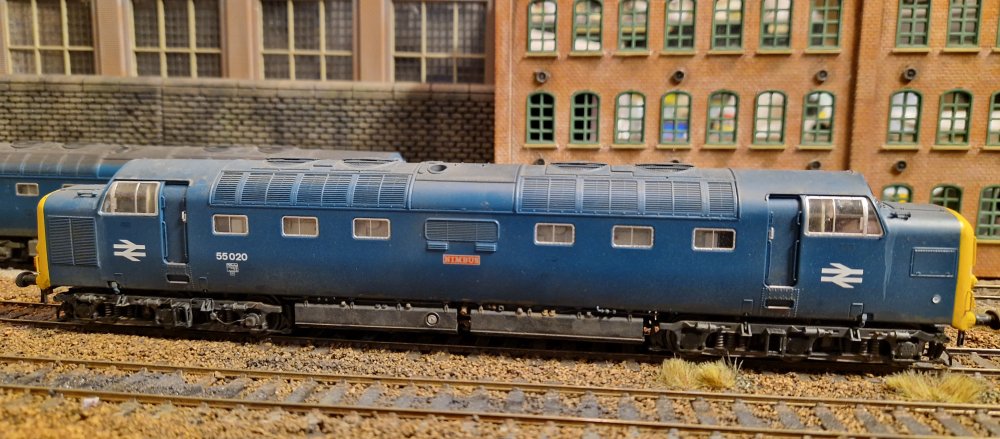 Next up is an Accurascale Class 55 Deltic, which comes from the factory without the bogie
chains fitted, making it easier to pop off the bogie frame assembly in one piece. The whole
wheel change took only 5 minutes this time and I didn't break anything! Wheels painted with
Tamiya red brown. I used exactly the same techniques as the 56 described above using the same
paints and the same layers. There is a dash of 50% IPA / Archive X Grime (light grey) used for
the wiper wash that dribbles down the sides of the nose on all Deltics.
Next up is an Accurascale Class 55 Deltic, which comes from the factory without the bogie
chains fitted, making it easier to pop off the bogie frame assembly in one piece. The whole
wheel change took only 5 minutes this time and I didn't break anything! Wheels painted with
Tamiya red brown. I used exactly the same techniques as the 56 described above using the same
paints and the same layers. There is a dash of 50% IPA / Archive X Grime (light grey) used for
the wiper wash that dribbles down the sides of the nose on all Deltics.
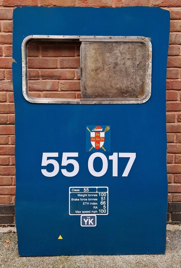 Now for some 1:1 scale modelling - this is the most ambitious piece I have ever made, a side
section of a Deltic. I made a wooden frame, similar in style to a baseboard and skinned it with
3mm hardboard cut to shape with a jigsaw, and added some tumblehome so it's not a flat surface.
It's painted with BR blue enamel paint with very slight rust weathering in places, as the client
wanted it in a clean condition. The decals are all custom cut and the York crest is scanned off
an original. The data panel was drawn up in Photoshop and printed from vinyl, with wonky numbers
as the originals were hand stuck on and never straight. It has my original number 18 Ballymoss
window in it for the photo, but the client will add his original number 17 Durham Light Infantry
window into it.
Now for some 1:1 scale modelling - this is the most ambitious piece I have ever made, a side
section of a Deltic. I made a wooden frame, similar in style to a baseboard and skinned it with
3mm hardboard cut to shape with a jigsaw, and added some tumblehome so it's not a flat surface.
It's painted with BR blue enamel paint with very slight rust weathering in places, as the client
wanted it in a clean condition. The decals are all custom cut and the York crest is scanned off
an original. The data panel was drawn up in Photoshop and printed from vinyl, with wonky numbers
as the originals were hand stuck on and never straight. It has my original number 18 Ballymoss
window in it for the photo, but the client will add his original number 17 Durham Light Infantry
window into it.
![]()
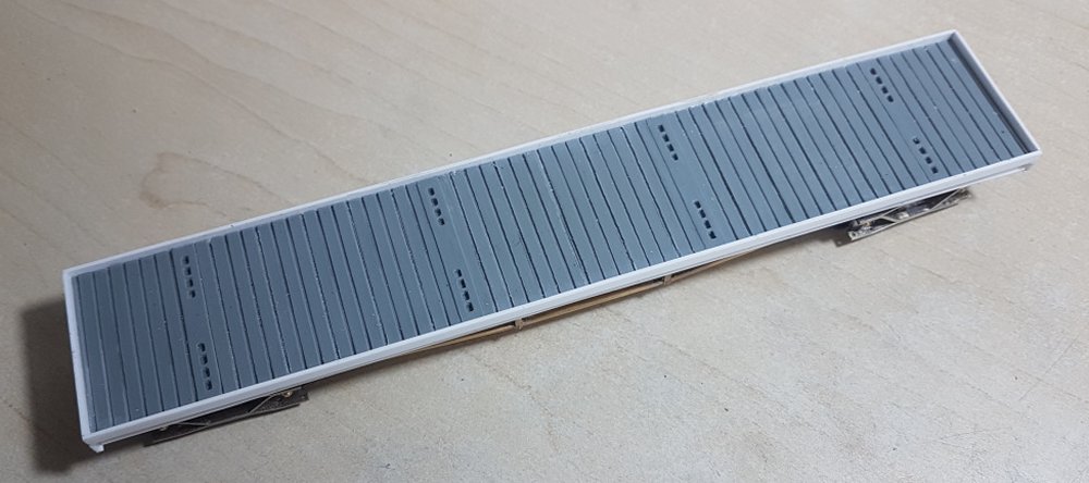
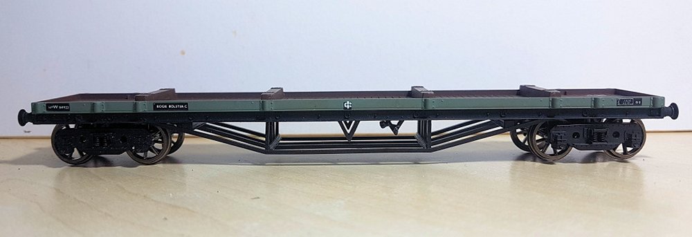 The Mainline rendition of a GWR MACAW B, introduced way back in 1980, forms the basis for a
number of projects to replicate later Bogie Bolster C wagons built by British Railways in
the early 1960s which, like their projected model counterparts, take their inspiration from
the GWR design.
The Mainline rendition of a GWR MACAW B, introduced way back in 1980, forms the basis for a
number of projects to replicate later Bogie Bolster C wagons built by British Railways in
the early 1960s which, like their projected model counterparts, take their inspiration from
the GWR design.
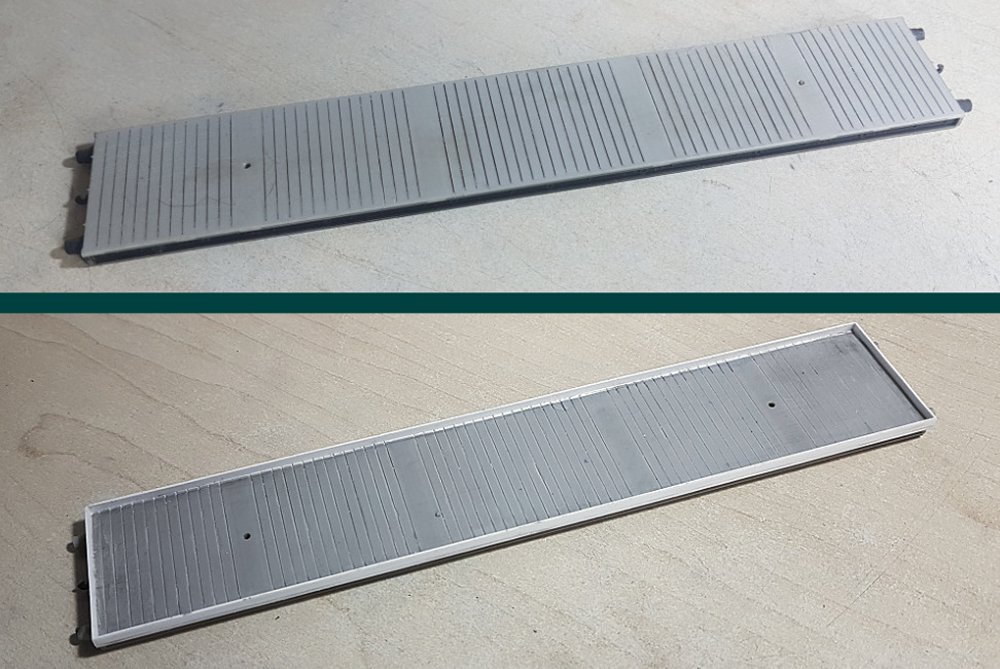
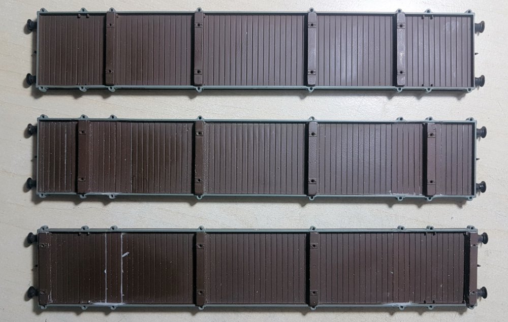 The GWR designs along with BR built types carried adjustable bolsters so with a number of
vehicles planned thoughts turned to depicting their bolsters in a similar fashion to add a
little variety. The top body is in original condition whilst the middle and lower ones show
the outer pair of bolsters in their alternative positions.
The GWR designs along with BR built types carried adjustable bolsters so with a number of
vehicles planned thoughts turned to depicting their bolsters in a similar fashion to add a
little variety. The top body is in original condition whilst the middle and lower ones show
the outer pair of bolsters in their alternative positions.
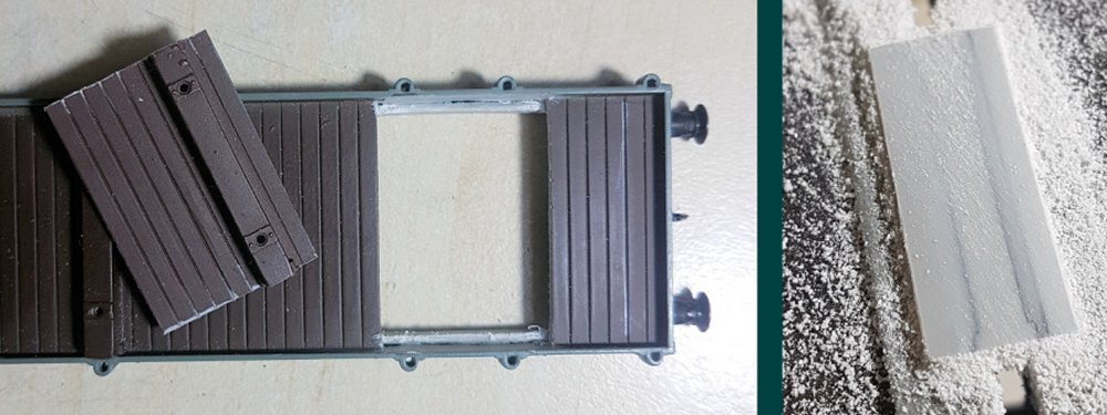 A spare body was sourced and used to create 'plug in' sections. The recipient vehicle
obviously required a hole into which the section could be fitted but a word of caution; the
floor and solebars of the model are a single moulding and as the solebars are inset from the
sides of the body then creating the hole using the inside of the body as a guide would lead
to a catastrophic loss of solebar! Very careful cutting / scraping with a scalpel allows the
removal of the floor to the level of the top of the solebar and any discrepancy can be catered
for by filing a recess on the rear of the plug in section. For a vehicle with the bolsters at
the very ends of the interior, the original bolster is removed and replaced with a plain
section of planking whilst the new bolster is created by filing away the floor beneath it and
simply placing it onto the existing floor. In this way the two new arrangements required three
bodies but in carrying out the operation it was found that the planking is not evenly spaced;
only the two inner bolsters from the donor body are suitable for replacing outer bolsters in
the middle outer position!
A spare body was sourced and used to create 'plug in' sections. The recipient vehicle
obviously required a hole into which the section could be fitted but a word of caution; the
floor and solebars of the model are a single moulding and as the solebars are inset from the
sides of the body then creating the hole using the inside of the body as a guide would lead
to a catastrophic loss of solebar! Very careful cutting / scraping with a scalpel allows the
removal of the floor to the level of the top of the solebar and any discrepancy can be catered
for by filing a recess on the rear of the plug in section. For a vehicle with the bolsters at
the very ends of the interior, the original bolster is removed and replaced with a plain
section of planking whilst the new bolster is created by filing away the floor beneath it and
simply placing it onto the existing floor. In this way the two new arrangements required three
bodies but in carrying out the operation it was found that the planking is not evenly spaced;
only the two inner bolsters from the donor body are suitable for replacing outer bolsters in
the middle outer position!
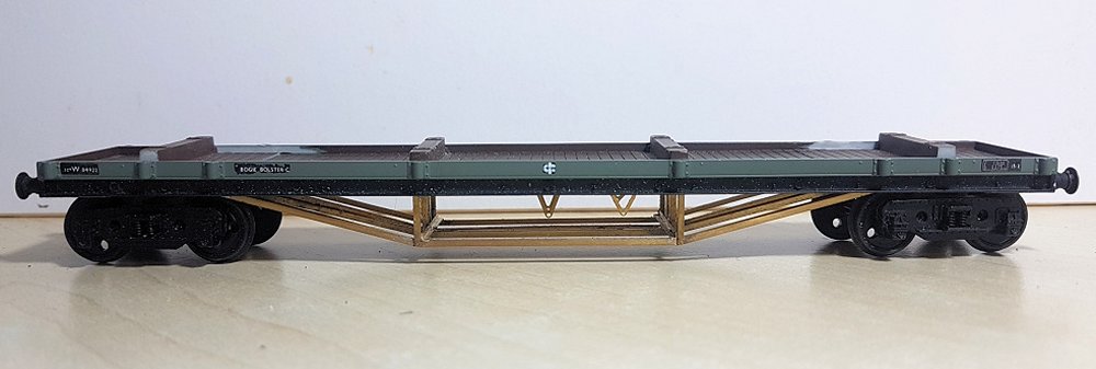 As it comes the Mainline models carry D/C brakes which are not correct for later BR built
wagons and in some cases the plastic underframe trussing is prone to breakage or distortion.
A solution to both of these problems is found by using a Rumney Models etched brass replacement.
Justin's C.05 etch caters for a large number of variants: GWR D/C, unfitted lever or two
arrangements for lever vacuum braked vehicles.
As it comes the Mainline models carry D/C brakes which are not correct for later BR built
wagons and in some cases the plastic underframe trussing is prone to breakage or distortion.
A solution to both of these problems is found by using a Rumney Models etched brass replacement.
Justin's C.05 etch caters for a large number of variants: GWR D/C, unfitted lever or two
arrangements for lever vacuum braked vehicles.
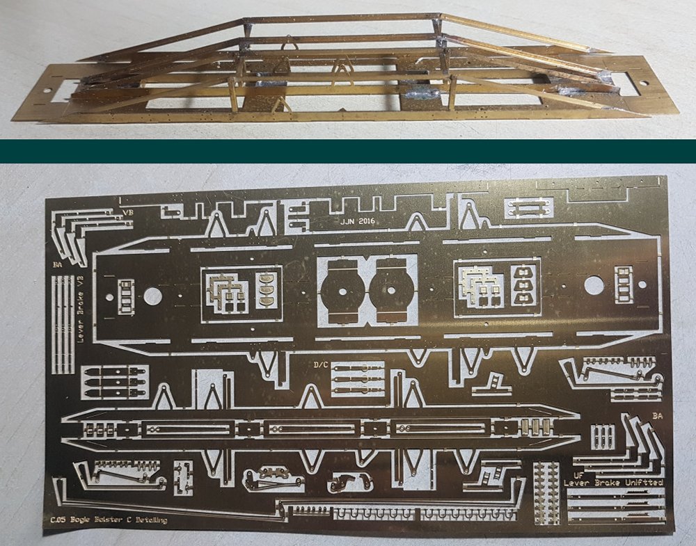 As with all of Justin's offerings, assembly is fairly straight forward but care is needed to
ensure the relevant brake lever Vs for your chosen braking system are not removed / left in situ!
As with all of Justin's offerings, assembly is fairly straight forward but care is needed to
ensure the relevant brake lever Vs for your chosen braking system are not removed / left in situ!
 One issue with the Mainline offering is that the fitted metal ballast weights sit between the
bogies rather than directly above them so to try and alleviate this I utilised the following
procedure. The reel like brass components are known as Chicago screws and are used for book
binding amongst other things (mine were retrieved from defunct circuit diagram books). Each
two piece item measures 8.5mm in height with a head diameter of 9.5mm and an internal thread of
4mm and can be used as they are or modified depending on the bogies being used. To provide the
necessary weight 1.5mm thick brass sheet has been formed to size into which the modified
Chicago screw has been soldered - using such thick brass necessitates the use of a blow torch
rather than a soldering iron!
One issue with the Mainline offering is that the fitted metal ballast weights sit between the
bogies rather than directly above them so to try and alleviate this I utilised the following
procedure. The reel like brass components are known as Chicago screws and are used for book
binding amongst other things (mine were retrieved from defunct circuit diagram books). Each
two piece item measures 8.5mm in height with a head diameter of 9.5mm and an internal thread of
4mm and can be used as they are or modified depending on the bogies being used. To provide the
necessary weight 1.5mm thick brass sheet has been formed to size into which the modified
Chicago screw has been soldered - using such thick brass necessitates the use of a blow torch
rather than a soldering iron!
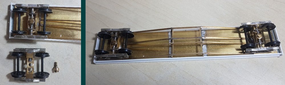
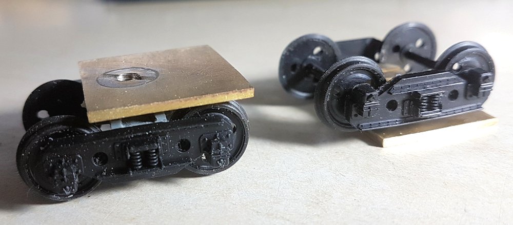 Seen here are original Mainline GWR plate back bogies married to their new brass weighted
assemblies. The plastic frames have been drilled out to accept brass pinpoint bearings but in
order to get the new Alan Gibson axles to run freely approx. 0.2mm was removed from each internal
face. The bogie pivot point utilises one taken from a redundant Cambrian kit.
Seen here are original Mainline GWR plate back bogies married to their new brass weighted
assemblies. The plastic frames have been drilled out to accept brass pinpoint bearings but in
order to get the new Alan Gibson axles to run freely approx. 0.2mm was removed from each internal
face. The bogie pivot point utilises one taken from a redundant Cambrian kit.
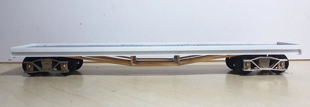 It was intended to create a former LMS 30T Bogie Bolster C adopting the same method already
outlined but such vehicles were wider than their GWR cousins. Originally a MR design, the LMS
carried it forward as their P11 design with P11A following the same format but the later thirty
P11C vehicles were slightly wider at 8' 8" rather than 8' 4" as before (GWR and BR BBCs were
7' 8" in width). As well as being wider in the body the underframe trussing was shallower and
at a different spacing to that catered for by the Rumney etch and so a scratch approach was taken.
It was intended to create a former LMS 30T Bogie Bolster C adopting the same method already
outlined but such vehicles were wider than their GWR cousins. Originally a MR design, the LMS
carried it forward as their P11 design with P11A following the same format but the later thirty
P11C vehicles were slightly wider at 8' 8" rather than 8' 4" as before (GWR and BR BBCs were
7' 8" in width). As well as being wider in the body the underframe trussing was shallower and
at a different spacing to that catered for by the Rumney etch and so a scratch approach was taken.
 As well as increasing in width, the wooden floor of P11 vehicles used slightly wider 7" planking
with gaps between to allow water to drain away so an unused Cambrian C28 kit for a BR 50T BORAIL
EC yielded its floor, suitably cut and shut to match the bolster positions. The sides and ends
were then formed from Evergreen 116 strip (15 x 125 thou / 0.75 x 3.2mm) which gave a body width
of 33mm or 8' 3".
As well as increasing in width, the wooden floor of P11 vehicles used slightly wider 7" planking
with gaps between to allow water to drain away so an unused Cambrian C28 kit for a BR 50T BORAIL
EC yielded its floor, suitably cut and shut to match the bolster positions. The sides and ends
were then formed from Evergreen 116 strip (15 x 125 thou / 0.75 x 3.2mm) which gave a body width
of 33mm or 8' 3".
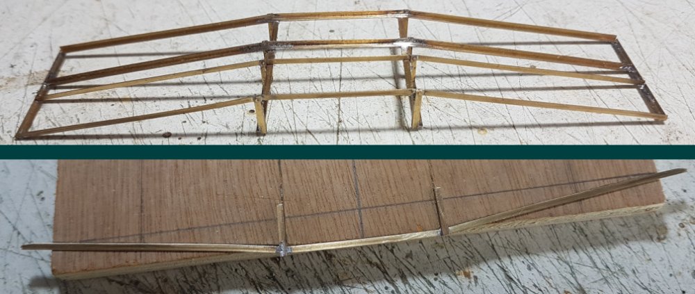 As stated earlier the underframe trussing is both shallower and at a different spacing to GWR
/ BR wagons so a wooden jig was created to achieve relatively similar components which were
then soldered together to provide the trussing unit.
As stated earlier the underframe trussing is both shallower and at a different spacing to GWR
/ BR wagons so a wooden jig was created to achieve relatively similar components which were
then soldered together to provide the trussing unit.
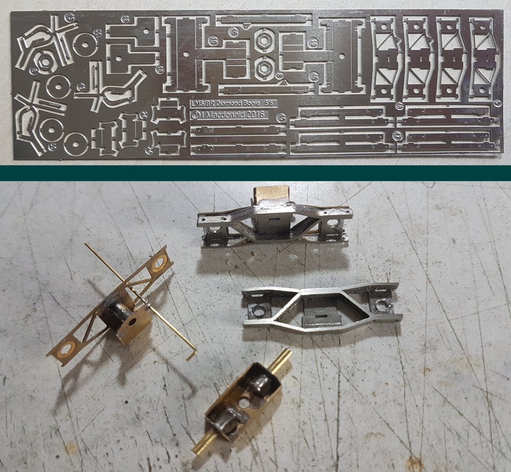 LMS bar frame (or Diamond) bogies with a 5' 6" wheelbase were fitted to their BBCs. Fortunately
Ian Macdonald (macgeordie on RMweb) created etched versions for these when designing his kit
for diagram 2/680 TRESTROL AD wagons and he was kind enough to provide me with a number of
etches to cover this eventuality! Ian's kits, like Justin's, are very well thought out but I
deviated from the provided build method as if followed the stiffness of the bogie frames
preclude being able to remove the wheelsets if required. In order to make them removable
should it be necessary I have utilised a Masokits brass etch (Part No. 9.04) which covers for
a compensated bar frame bogie which was then fitted to Ian's bogie sideframes to provide this
capability. Another slight modification is the removal of the braking attachment points as on
bogie bolsters the brake levers were attached to the trussing / solebars rather than to the
bogies as was the case for Trestrols.
LMS bar frame (or Diamond) bogies with a 5' 6" wheelbase were fitted to their BBCs. Fortunately
Ian Macdonald (macgeordie on RMweb) created etched versions for these when designing his kit
for diagram 2/680 TRESTROL AD wagons and he was kind enough to provide me with a number of
etches to cover this eventuality! Ian's kits, like Justin's, are very well thought out but I
deviated from the provided build method as if followed the stiffness of the bogie frames
preclude being able to remove the wheelsets if required. In order to make them removable
should it be necessary I have utilised a Masokits brass etch (Part No. 9.04) which covers for
a compensated bar frame bogie which was then fitted to Ian's bogie sideframes to provide this
capability. Another slight modification is the removal of the braking attachment points as on
bogie bolsters the brake levers were attached to the trussing / solebars rather than to the
bogies as was the case for Trestrols.
 Again Chicago screws were used to create the bogie pivot points and to allow the bogies to
pivot correctly a shouldered screw arrangement was concocted. 1.5mm thick brass is again
used for the bogie assemblies but the trussing assembly has been soldered to a more prudent
20 thou (0.25mm) thick bed plate.
Again Chicago screws were used to create the bogie pivot points and to allow the bogies to
pivot correctly a shouldered screw arrangement was concocted. 1.5mm thick brass is again
used for the bogie assemblies but the trussing assembly has been soldered to a more prudent
20 thou (0.25mm) thick bed plate.
 Another Bogie Bolster inspired project is a BR diagram 1/480 BORAIL WE, fifty of which were
built by Swindon as a smaller version of GWR GANE A wagons. At 45' in length they were
comparable to Bogie Bolster Cs but could carry a higher payload of 40 tons rather than 30
tons although their use as Borails was to be short lived with them being branded as Bogie
Bolster C instead. As per the LMS P11 vehicles they were 8' 4" wide but unlike their LMS
predecessors the underframes were identical to the GWR / BR Bogie Bolster Cs. To this end
a Mainline body was butchered to remove the sides and all bolster detailing onto which
replacement Evergreen strip could be grafted. In order to maintain the correct dimensions
a strip of Evergreen 121 (20 x 30 thou) was first stuck to each side and then scribed to
match the existing planking. Another strip of 121 was then overlaid onto the scribed section
before Evergreen 124 (20 x 80 thou) was placed at right angles to this section to create the
sides. All in all a convoluted process but providing a 33.5mm / 8' 4 1/2" wide body!
Another Bogie Bolster inspired project is a BR diagram 1/480 BORAIL WE, fifty of which were
built by Swindon as a smaller version of GWR GANE A wagons. At 45' in length they were
comparable to Bogie Bolster Cs but could carry a higher payload of 40 tons rather than 30
tons although their use as Borails was to be short lived with them being branded as Bogie
Bolster C instead. As per the LMS P11 vehicles they were 8' 4" wide but unlike their LMS
predecessors the underframes were identical to the GWR / BR Bogie Bolster Cs. To this end
a Mainline body was butchered to remove the sides and all bolster detailing onto which
replacement Evergreen strip could be grafted. In order to maintain the correct dimensions
a strip of Evergreen 121 (20 x 30 thou) was first stuck to each side and then scribed to
match the existing planking. Another strip of 121 was then overlaid onto the scribed section
before Evergreen 124 (20 x 80 thou) was placed at right angles to this section to create the
sides. All in all a convoluted process but providing a 33.5mm / 8' 4 1/2" wide body!
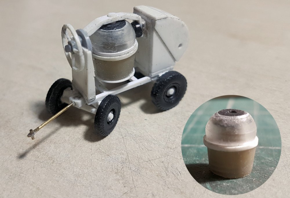 In between playing with bogies(!) a towed cement mixer has been knocked up by judicious use
of plasticard and strip although the actual drum utilises bits from redundant ball point pens!
In between playing with bogies(!) a towed cement mixer has been knocked up by judicious use
of plasticard and strip although the actual drum utilises bits from redundant ball point pens!
![]()
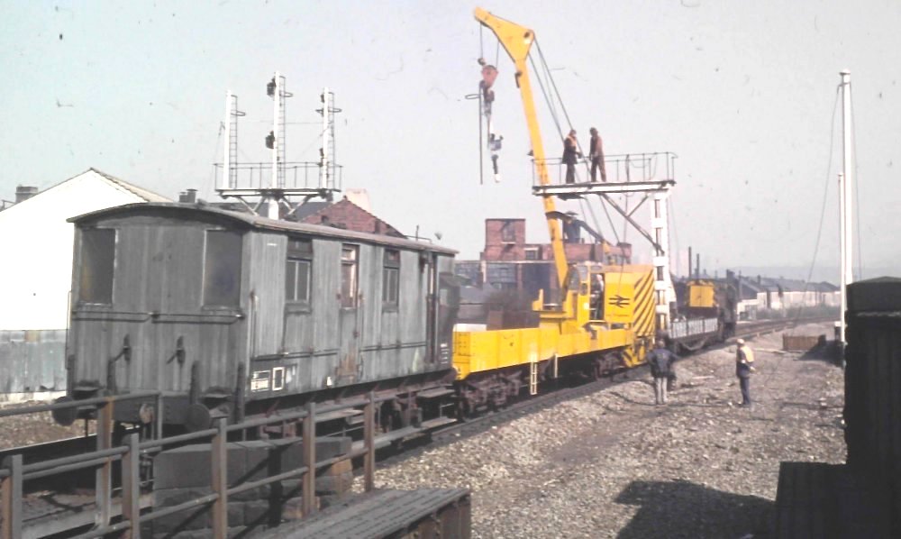 LNER designed Ballast Brake DE544441 is seen with a works train at Heeley, just south of
Sheffield during the summer of 1973, after the new colour light signals had been
installed on the Midland Main Line. Photograph by Mike Whitchurch.
LNER designed Ballast Brake DE544441 is seen with a works train at Heeley, just south of
Sheffield during the summer of 1973, after the new colour light signals had been
installed on the Midland Main Line. Photograph by Mike Whitchurch.
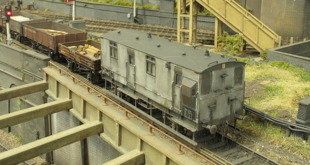 The LNER diagram 203 design from 1948 is described as a 20t Ballast Brake and Workmen's Van.
One end was dedicated to the guard, where standard lookout duckets and a handbrake column
were provided. The workmen's area was entered by a separate door to a much larger area.
The LNER diagram 203 design from 1948 is described as a 20t Ballast Brake and Workmen's Van.
One end was dedicated to the guard, where standard lookout duckets and a handbrake column
were provided. The workmen's area was entered by a separate door to a much larger area.
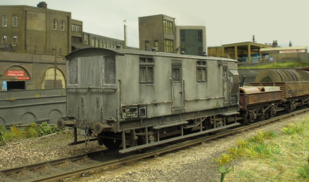 This model has been produced from one of Jonny's 3D prints (available as a free download from
Thingiverse), shown
here after painting, glazing, weathering and fitting of handrails. Dimples are provided on
the print to assist with the positioning of handrails.
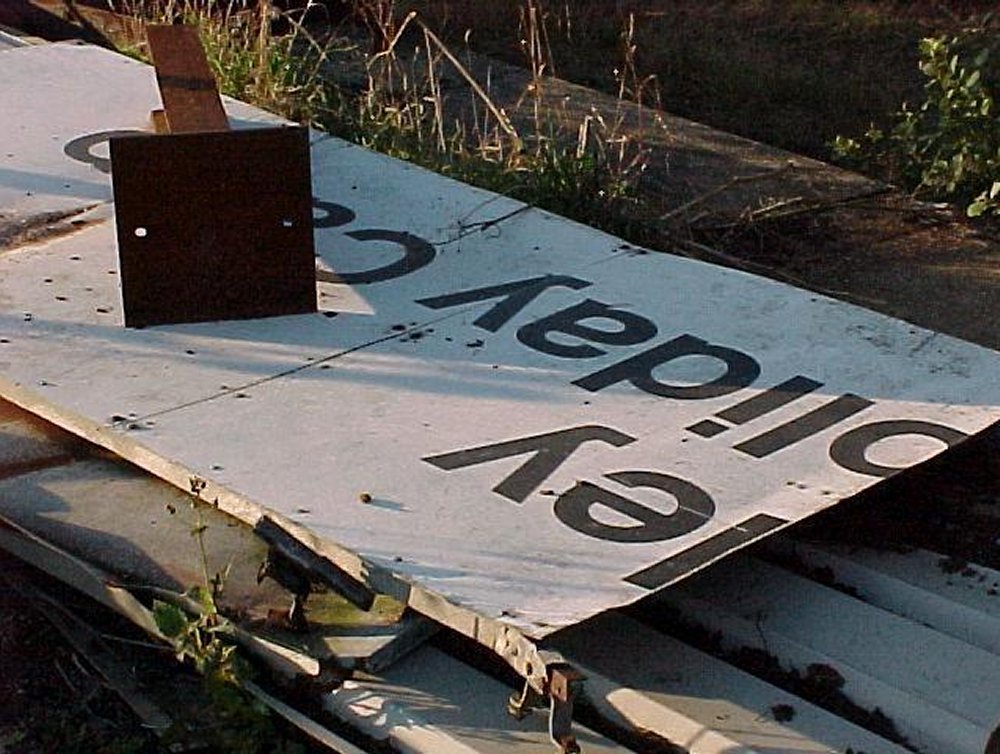
Having recently uncovered some images in my archive, a new page has been created showing
the part demolished Butlin's holiday camp at Filey and the adjoining railway station in 1998.
The camp and its demise are well documented elsewhere, so hopefully these additional images
may be of interest. Please click on the image above to view the gallery.
This model has been produced from one of Jonny's 3D prints (available as a free download from
Thingiverse), shown
here after painting, glazing, weathering and fitting of handrails. Dimples are provided on
the print to assist with the positioning of handrails.
Having recently uncovered some images in my archive, a new page has been created showing
the part demolished Butlin's holiday camp at Filey and the adjoining railway station in 1998.
The camp and its demise are well documented elsewhere, so hopefully these additional images
may be of interest. Please click on the image above to view the gallery.
![]()
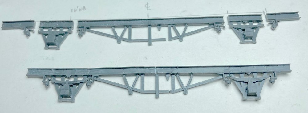 After several months of working on my South American narrow gauge layout I felt the urge to
return to some EM modelling. Something that had been on the to-do list for some time was one
of the rather obscure GWR pump vans. Just five of these unusual vehicles were built but
information and photographs are few and far between. With just the length, width and wheelbase
to work from this was the starting point - a Parkside Fruit D. Here we see the cuts needed to
reduce the original wheelbase to the 14ft of the pump van. The cuts also reduced the length of
the spring mouldings.
After several months of working on my South American narrow gauge layout I felt the urge to
return to some EM modelling. Something that had been on the to-do list for some time was one
of the rather obscure GWR pump vans. Just five of these unusual vehicles were built but
information and photographs are few and far between. With just the length, width and wheelbase
to work from this was the starting point - a Parkside Fruit D. Here we see the cuts needed to
reduce the original wheelbase to the 14ft of the pump van. The cuts also reduced the length of
the spring mouldings.
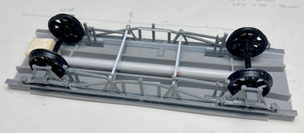 With the length reduced and the chassis parts reassembled a vague representation of some of
the underframe pipework (very much lost in shadow on the original works photos in two of the
OPC / Russell GWR wagon books). The wagons seem to have been altered quite drastically over
the years and the only images I’ve so far found after the 1940s originals were from the old
‘Per Way Yard’ alongside the top sidings at Barry (always in the background to photos of the
steam locos sold to Woodhams). By then the corridor connections and the substantial end pipework
had gone. Had they latterly been converted to mobile generator sets? That remains a mystery.
With the length reduced and the chassis parts reassembled a vague representation of some of
the underframe pipework (very much lost in shadow on the original works photos in two of the
OPC / Russell GWR wagon books). The wagons seem to have been altered quite drastically over
the years and the only images I’ve so far found after the 1940s originals were from the old
‘Per Way Yard’ alongside the top sidings at Barry (always in the background to photos of the
steam locos sold to Woodhams). By then the corridor connections and the substantial end pipework
had gone. Had they latterly been converted to mobile generator sets? That remains a mystery.
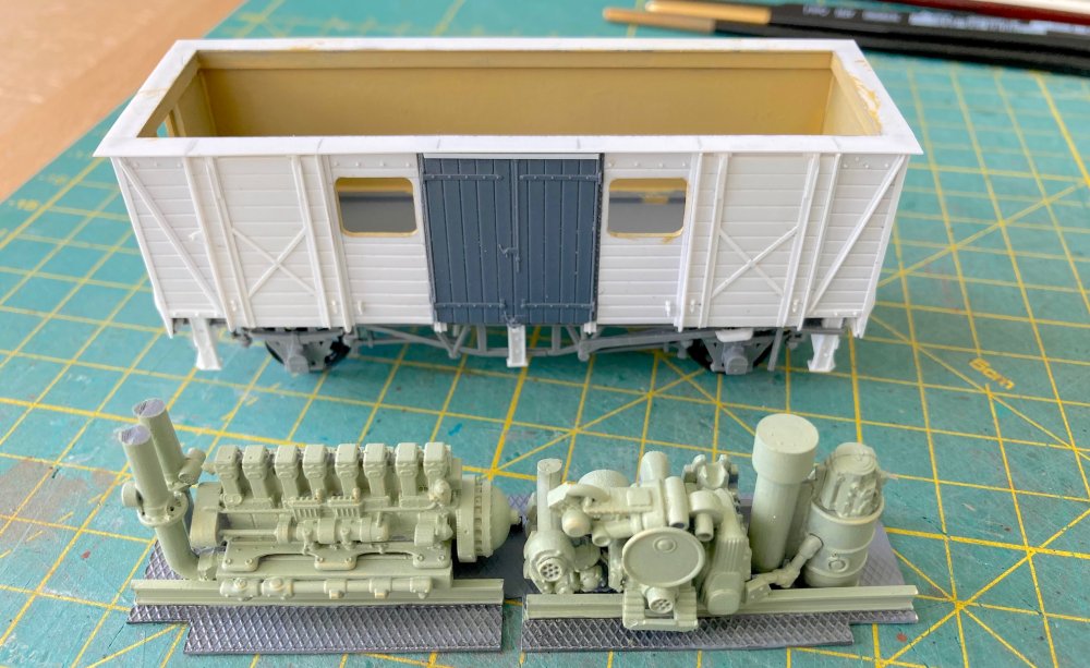
 With the chassis up and running and the three chunky supports fitted, presumably intended for
packing when the hefty diesel set was running, it was time to think about the bodywork. Both
sides were completely different, which made for an unusual build. The side doors came from a
Ratio GWR van kit - the ones with the Parkside Fruit D were four planks wide whereas the pump
van was five planks. The ends were from the Fruit D with the pair of moulded ventilators
removed with knives and a sander.
With the chassis up and running and the three chunky supports fitted, presumably intended for
packing when the hefty diesel set was running, it was time to think about the bodywork. Both
sides were completely different, which made for an unusual build. The side doors came from a
Ratio GWR van kit - the ones with the Parkside Fruit D were four planks wide whereas the pump
van was five planks. The ends were from the Fruit D with the pair of moulded ventilators
removed with knives and a sander.
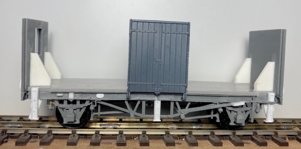
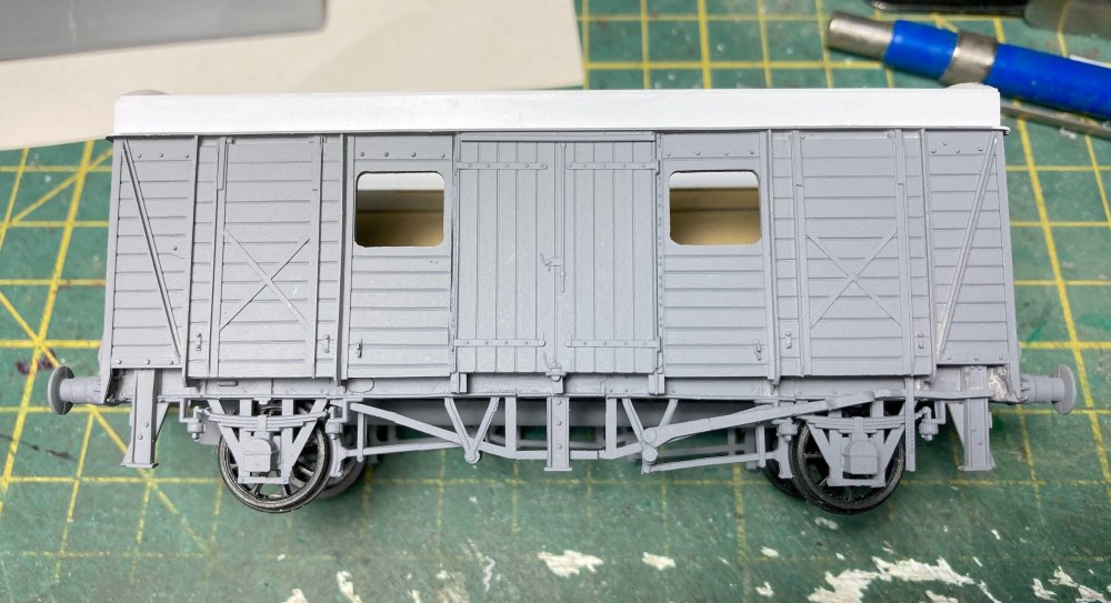
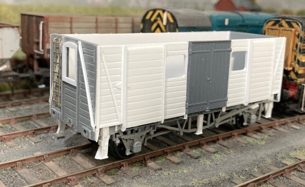 Here we see the van with the sides fitted. In addition to the two standard van doors this side
also included a pair of lift up doors. The ends originally featured gangway connections but by
the 1966 images these had gone from the Barry van. Most unusually three of the van bodies made
an unexpected reappearance in 1988 outside some soon to be demolished Dock Engineer sheds in
Cardiff Docks. Where they had been for the previous 20-odd years is another of the mysteries
surrounding these five vans! Of the three bodies one example had an additional window and ladder
on the end and this combination was copied for the model. The sides are made from 40-thou and
30-thou styrene scribed using a Revell panel line tool along with a quantity of Evergreen plastic
strip for the other details.
Here we see the van with the sides fitted. In addition to the two standard van doors this side
also included a pair of lift up doors. The ends originally featured gangway connections but by
the 1966 images these had gone from the Barry van. Most unusually three of the van bodies made
an unexpected reappearance in 1988 outside some soon to be demolished Dock Engineer sheds in
Cardiff Docks. Where they had been for the previous 20-odd years is another of the mysteries
surrounding these five vans! Of the three bodies one example had an additional window and ladder
on the end and this combination was copied for the model. The sides are made from 40-thou and
30-thou styrene scribed using a Revell panel line tool along with a quantity of Evergreen plastic
strip for the other details.
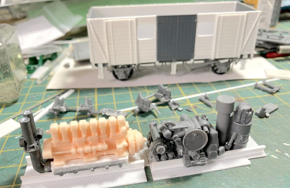 With the body well advanced it was time for a representation of the interior. With this only
being visible through three small windows this didn’t have to be totally accurate and was based
very loosely on the arrangement seen in one of the Russell books. The resin engine came from an
online supplier and is actually a class 03 Gardner power plant. The rest is cobbled together
from a sprue of fantasy war-games parts intended for a selection of Mad Max-style off-road vehicles!
With the body well advanced it was time for a representation of the interior. With this only
being visible through three small windows this didn’t have to be totally accurate and was based
very loosely on the arrangement seen in one of the Russell books. The resin engine came from an
online supplier and is actually a class 03 Gardner power plant. The rest is cobbled together
from a sprue of fantasy war-games parts intended for a selection of Mad Max-style off-road vehicles!
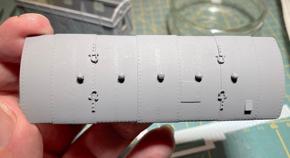
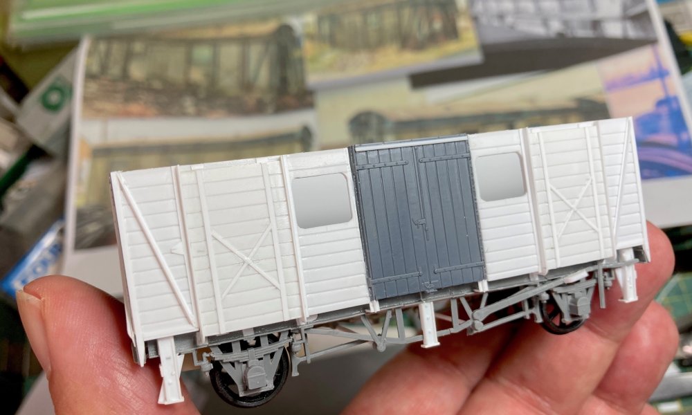 The completed window side before the addition of lots of rivets. Still to come is the Iron
Mink-style body extension and roof. Beyond is the selection of images of the three Cardiff vans
that appeared briefly in 1988 before succumbing to the scrap man within days. These were used
to decide on the paint scheme for the completed van.
The completed window side before the addition of lots of rivets. Still to come is the Iron
Mink-style body extension and roof. Beyond is the selection of images of the three Cardiff vans
that appeared briefly in 1988 before succumbing to the scrap man within days. These were used
to decide on the paint scheme for the completed van.
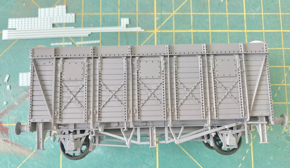
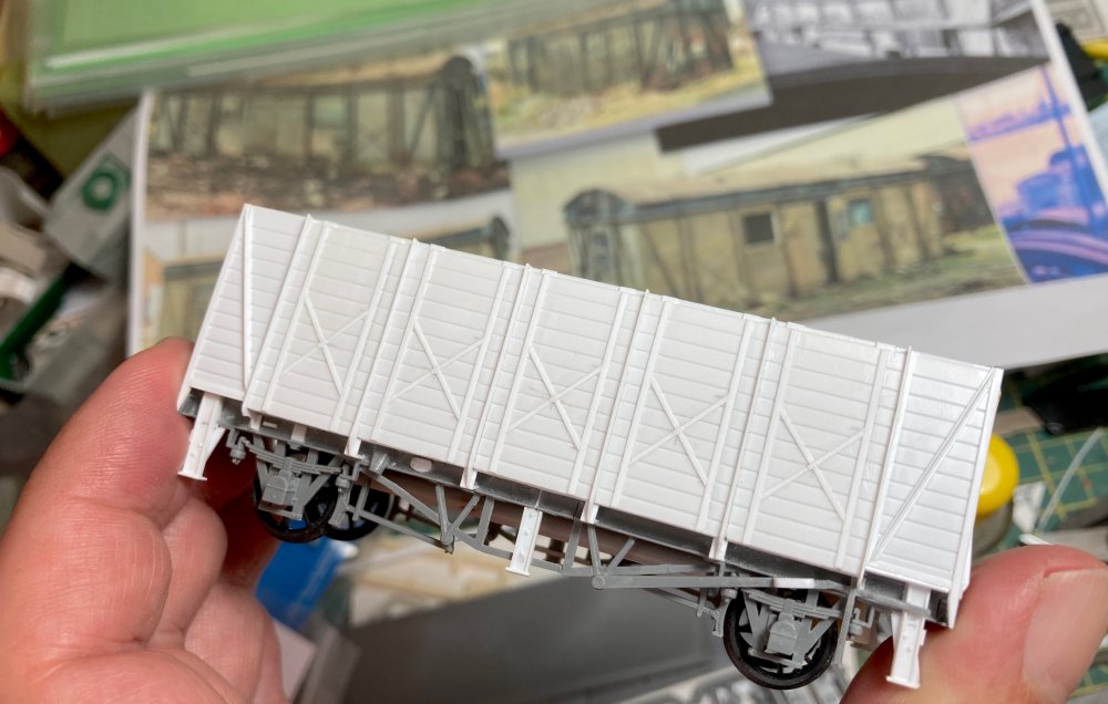 Here is the opposite face with the five lift-up doors that provided access to the engine and
pump on this side. Again awaiting rivets and the side extension.
Here is the opposite face with the five lift-up doors that provided access to the engine and
pump on this side. Again awaiting rivets and the side extension.
 The distinctive lip between the wooden body and the soon to appear steel top half has been
fitted. Also the interior has received a coat of paint and, once the windows are fitted, will
be glued permanently inside.
The distinctive lip between the wooden body and the soon to appear steel top half has been
fitted. Also the interior has received a coat of paint and, once the windows are fitted, will
be glued permanently inside.
 The body has now been primed, which showed up any issues that needed filling or sanding. The
bodyside extension is now fitted ready for further detailing.
The body has now been primed, which showed up any issues that needed filling or sanding. The
bodyside extension is now fitted ready for further detailing.
 The van now with the top section fitted, features a lot of rivets and the only sensible way
to do this was to use the excellent (and now sadly discontinued) Archer rivet strips. The vans
feature various pitches of rivets and the sheets catered admirably for these and so it was out
with a small dish of water, a new scalpel blade and some very fine tweezers. Oh, and a good
dose of patience. A few rows were slid into place and tamped down and then varnished before the
next group was tackled, this being an attempt to stop too many lifting off while fitting the
others - several did, in fact, disappear never to be seen again. But it did get finished.
The van now with the top section fitted, features a lot of rivets and the only sensible way
to do this was to use the excellent (and now sadly discontinued) Archer rivet strips. The vans
feature various pitches of rivets and the sheets catered admirably for these and so it was out
with a small dish of water, a new scalpel blade and some very fine tweezers. Oh, and a good
dose of patience. A few rows were slid into place and tamped down and then varnished before the
next group was tackled, this being an attempt to stop too many lifting off while fitting the
others - several did, in fact, disappear never to be seen again. But it did get finished.
 The roof, essentially an extended Iron Mink style, was made from the original Fruit D example
with a careful cut to fall beneath the line of one of the three raised sections (made of
10-thou sheet). The four lifting shackles (presumably enabling the pump van to be lifted by
crane to whatever part of the docks system it was needed in) were styrene strip, slightly
kinked at the top end with etched shackles added. Also added were the five cast ventilators.
And, of course, a lot more Archer rivets.
The roof, essentially an extended Iron Mink style, was made from the original Fruit D example
with a careful cut to fall beneath the line of one of the three raised sections (made of
10-thou sheet). The four lifting shackles (presumably enabling the pump van to be lifted by
crane to whatever part of the docks system it was needed in) were styrene strip, slightly
kinked at the top end with etched shackles added. Also added were the five cast ventilators.
And, of course, a lot more Archer rivets.
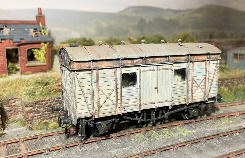 The finished van (window side) is parked up in the back siding at Morfa Bank. The three that
reappeared in 1988 were all in different liveries. One was in BR engineer’s olive green, one
was in patchy gulf red and black livery and one was in very worn and faded BTDB light blue
colours. The latter was the version that was picked for my Port Talbot Docks van with the
white lettering barely legible. The weathering was also unusual as the bottom part was
weathered wood while the top part was very weathered and rusty steel.
The finished van (window side) is parked up in the back siding at Morfa Bank. The three that
reappeared in 1988 were all in different liveries. One was in BR engineer’s olive green, one
was in patchy gulf red and black livery and one was in very worn and faded BTDB light blue
colours. The latter was the version that was picked for my Port Talbot Docks van with the
white lettering barely legible. The weathering was also unusual as the bottom part was
weathered wood while the top part was very weathered and rusty steel.
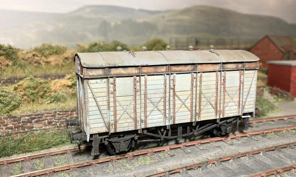 And here’s the other side with the lift up doors. Again very faded from being parked up with,
presumably, very little use. Such a specialised wagon won’t see a lot of outings on Morfa Bank,
but when it does appear it will, hopefully, provoke some interesting comments. It’s not often
you get to build a piece of stock where each side, and end, is completely different to the
other. Or one with so little prototype information available.
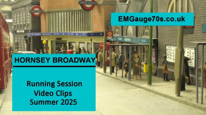
Please click on the above image to view the Summer 2025 running session video.
And here’s the other side with the lift up doors. Again very faded from being parked up with,
presumably, very little use. Such a specialised wagon won’t see a lot of outings on Morfa Bank,
but when it does appear it will, hopefully, provoke some interesting comments. It’s not often
you get to build a piece of stock where each side, and end, is completely different to the
other. Or one with so little prototype information available.
Please click on the above image to view the Summer 2025 running session video.